Nomenclature
a) Pneumatic Cylindersb) Hydraulic Cylinders
c) Air Cylinders
d) Hollow Pneumatic / Hydraulic Cylinders
Description & Features:
The Sonalkar Actuator Units are designed and manufactures keeping in mind two basic consideration
 Operator Safety. This is the most important design consideration. The Actuators are guaranteed to work safely at high pressures and speeds. The feeder lines are also designed to with stand high line pressures at very high speeds.
Compact and light weight. The Actuators are so designed to keep the dynamic load on the machine spindle to a minimum, thus reducing machine vibration and increasing spindle life.
The Actuator cylinder body is made of high quality aluminum alloy, and specially treated to withstand large loads. The piston is made of medium carbon steel, and then toughened.
The distributor shaft relates in a pres fitted bronze bush.
Lubricant is provided for self-lubrication of the distributor shaft. To prevent leakage at high speeds the cylinders are fitted with imported high speed bearings. The sealing kit and 'O' rings fitted inside the cylinder are specially made to ensure long cylinder life.
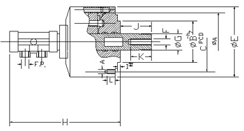
Rotating Pneumatic Cylinders with air-in-feed unit are available for an actuating pressure of 7kg/cm2. The size depends on operating force reuired. The cylinders are available in open and close type.
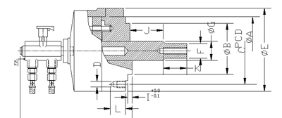
Rotating Hydraulic Cylinders are availalbe for actuating pressures upto 40kg/cm2. The cylinders are available in open, close and high speed open type.
Hollow High speed Cylinders with roller bearing are availalbe for high speed through-feed opearation.
Scope of Supply
The Sonalkar Hydraulic Power chuck System comprises.Hydraulic Chuck
> Hydraulic Cylinder
> Chuck flange
> Cylinder flange
> Drawbar & hoses
> Direction control valves
The Sonalkar Pneumatic Power Chuck System comprises > Pneumatic Chuck > Pneumatic Cylinder > Chuck flange > Cylinder flauge > Drawbar & hoses > Lubocontrol unit > Direction control valves and non-return valve